Promac LCD TV model# LCD-2051 powers up from stand-by, sound comes up and backlight lights up but set goes back to stand-by before picture appears.
Found some bulging 47uF/16V capacitors on power supply board on location C3 and C8. Replacing the capacitors restored normal operation to the set.
Wednesday, August 24, 2011


Thursday, June 16, 2011
Sony TV KV-21GMR1 power problem:SE115N error amp defect
Sony TV model# KV-21GMR1 is a dead set: no LED standby indicator light, +115V supply to horizontal output transistor measured only 27V and is pulsating.
The SMPS regulator IC STR-S6707 was replaced but still the +115v supply line is dropped.
Even when the horizontal output transistor is disconnected from the circuit the +115V supply will not increase.
An ohmmeter check on the SE115N error amplifier shows that it is internally open circuited.
Power was restored to the set when the SE115N was replaced.
The SMPS regulator IC STR-S6707 was replaced but still the +115v supply line is dropped.
Even when the horizontal output transistor is disconnected from the circuit the +115V supply will not increase.
An ohmmeter check on the SE115N error amplifier shows that it is internally open circuited.
Power was restored to the set when the SE115N was replaced.
Wednesday, June 15, 2011
Philips CTV 29PT2252/56A (L01.1A chassis)problem:intermittent pincushion distortion
This Philips TV model# 29PT2252/56A exhibited intermittent increase in picture width with pincushion distortion and blanking of picture.
A visual inspection of the printed circuit board reveals solder crack on pin 1 of pincushion transformer on board location 5465/5464/5463.
Resoldering of the cold solder on the pincushion transformer solved the problem of intermittent picture width and pincushion distortion.
A visual inspection of the printed circuit board reveals solder crack on pin 1 of pincushion transformer on board location 5465/5464/5463.
Resoldering of the cold solder on the pincushion transformer solved the problem of intermittent picture width and pincushion distortion.
Sunday, March 27, 2011
Microwave Oven Care and Maintenance Tips
 Image via Wikipedia
- Do not load more than the kilogram capacity rating of the microwave oven. It will put mechanical and electrical stress on both the turntable motor and the magnetron that heats the food.
- As much as possible put a cover on the food container when cooking to prevent food splashes to the oven cabinet and walling. Food splashes when heated burns and emits smoke and can damage the paint and metal of the oven cabinet.
- Clean the both the interior and exterior of the oven cabinet regularly to prevent corrosion and rust.
- Turn off or cancel the program timer first before opening the oven door. Sudden opening of oven door could blow the safety fuse.
- Unplug the microwave oven after use particularly models that use an electronic control panel which has digital display and electronic circuitry. These electronic parts are highly susceptible to damage caused by voltage spikes, power fluctuations and lightning strikes.
- Do not heat liquids using the microwave oven for more than 2 minutes. Do not use the microwave oven to boil water as this is a potential safety hazard.
- Do not run the microwave oven without any food or liquid to absorb the magnetron's energy. Energy emitted by the magnetron can feed back to itself and cause damage to magnetron's internal parts.
- Use microwavable food containers which uses plastic, ceramic or glass material. Never use metal containers or aluminum foil as microwave energy bounces off metallic materials and cause uneven heating and cooking of food.

Monday, February 7, 2011
Philips TV Service Mode
To access service mode in a Philips TV, press on the remote control keys:
0-6-2-5-9-6-OSD(i+) or
0-6-2-5-9-6-MENU.
The service mode will allow you to adjust picture Geometry and White Tone via remote.


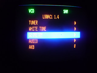
You can also adjust the option codes to configure drivers for the hardware components particularly the I2C devices..


0-6-2-5-9-6-OSD(i+) or
0-6-2-5-9-6-MENU.
The service mode will allow you to adjust picture Geometry and White Tone via remote.


You can also adjust the option codes to configure drivers for the hardware components particularly the I2C devices..


Friday, November 26, 2010
Sony TV KV-25JXR20 reduced horizontal width problem
The owner of a Sony TV with model number KV-25JXR20 complained of the reduced horizontal width of the picture of his TV. He also observed "blinking" of the picture which must be his description of intermittent blanking of the picture.
During my initial observation of the problem I also noticed that the vertical size of the picture is in overscan - or stretched - resulting to vertical mislinearity and the presence of red, blue and green blanking lines at the top edge of the picture.
I suspected capacitors with changed values in the vertical deflection circuit and the horizontal deflection or pin correction circuits. Since the TV is already in the vicinity of being ten years of age, I also considered the possibility of dry solder joints.
Since there was no obvious bulging capacitors in my initial inspection of the main PCB I proceeded to resolder the deflection circuits and some parts of the chopper transformer, filter capacitors and rectifier diodes in the secondary circuit of the power supply.
After the soldering exercise, I powered-up the TV again to check if the problem was solved. I was not much surprised to see that the problem still persists since there was not really any obvious cracked or dried up solder joints on the TV's circuit board.
Doing another visual inspection on the component side of the PCB, I noticed the slight bulge on the top of a filter capacitor that was sitting beside the chopper transformer. I desoldered the capacitor and found out that it is a 100uF/160V electrolytic capacitor on PCB location number C609. A look under the capacitor revealed signs of electrolyte leakage. With the capacitor leads still hot from contact with the soldering iron I can still see the electrolyte boiling out of one of the capacitor leads.
By replacing this capacitor only, I was able to solved both the problem with reduced horizontal width and vertical mislinearity.
During my initial observation of the problem I also noticed that the vertical size of the picture is in overscan - or stretched - resulting to vertical mislinearity and the presence of red, blue and green blanking lines at the top edge of the picture.
I suspected capacitors with changed values in the vertical deflection circuit and the horizontal deflection or pin correction circuits. Since the TV is already in the vicinity of being ten years of age, I also considered the possibility of dry solder joints.
Since there was no obvious bulging capacitors in my initial inspection of the main PCB I proceeded to resolder the deflection circuits and some parts of the chopper transformer, filter capacitors and rectifier diodes in the secondary circuit of the power supply.
After the soldering exercise, I powered-up the TV again to check if the problem was solved. I was not much surprised to see that the problem still persists since there was not really any obvious cracked or dried up solder joints on the TV's circuit board.
Doing another visual inspection on the component side of the PCB, I noticed the slight bulge on the top of a filter capacitor that was sitting beside the chopper transformer. I desoldered the capacitor and found out that it is a 100uF/160V electrolytic capacitor on PCB location number C609. A look under the capacitor revealed signs of electrolyte leakage. With the capacitor leads still hot from contact with the soldering iron I can still see the electrolyte boiling out of one of the capacitor leads.
By replacing this capacitor only, I was able to solved both the problem with reduced horizontal width and vertical mislinearity.
Friday, July 23, 2010
Kolin TV Service Mode
| Chassis | Remote codes | To exit |
|---|---|---|
| I-Chassis | SLEEP-MUTE-DSP-MENU | DSP or SLEEP |
| K-Chassis | SLEEP-PIC-DSP-MENU. Press MENU to navigate pages. | SLEEP |
| M-Chassis | DSP-SLEEP-PIC. To select adjustment menu use CH+/CH- buttons. To enter the adjustment menus, use VOL+/VOL- | MENU |
Before doing adjustments, list down the adjustment items and their corresponding data so you can return the data to previous settings in case the new settings result to more problems.
Subscribe to:
Posts (Atom)